Intelligent Ground Vehicle Competition In addition to community outreach, the team continued work on our robot for the Intelligent Ground Vehicle Competition (IGVC) Rochester, Michigan which took place June 2nd to 5th. The vehicle needed to navigate the course autonomously while avoiding obstacles, following speed limits, and carrying a 20lb payload. The team was judged on the overall design of the robot, including functionality, originality, innovations, and other criteria. This was evaluated through a written report, oral presentation, and robot inspection. You can visit the competition website here: IGVC Our design report can be found here: Design Report
Mechanical Design
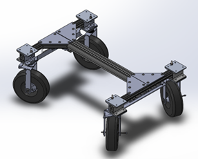
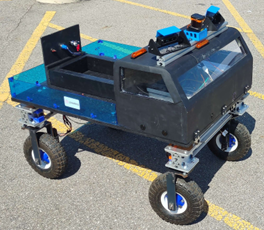
The mechanical sub-team is focused on making the robot's frame, chassis, drivetrain, and outer shell. This semester was heavily focused on the final design of all four sub-systems, the frame, steering system, wheel mounts, and outer shell. The frame consists of several pieces of 1 ½” T-Slot put together in an “I” shape. This provides much of the support for the drivetrain and electronic components, as well as the payload. Throughout the frame, aluminum brackets and plates are used to help provide support, along with mounting points for other components. The T-Slot also allows the chassis to be modular, allowing elements to be moved and adjusted as needed. The steering system that was designed is one of the mechanical innovations for this robot. The setup for the steering is similar to a dual-Ackerman system, with the added ability to strafe at a 45-degree angle. Through a set of curved linkages and a rack and pinion system, the turning radius of the robot was decreased to just under 3’. This system also works in tandem with the wheel mounts. Each wheel mount is connected to a linkage by a bolt, which is turned using both the linkages and a set of bearings. While each wheel is driven independently, they are turned simultaneously within pairs. Inspired by Japanese Kei Trucks, the outer shell provides aesthetics, some water resistance, and sensor mounts. The cab was made in several sections, using large-bed 3D printers. Attached to the top is a piece of T-slot that further increases modularity and allows the positions of the sensors to be adjusted as needed. In the bed, there is also a frame to hold the payload, and at the back, a panel for the start and e-stop switches.

 CAD model of the final chassis and the completed robot at competition!
Electrical Design
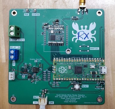
The electrical sub-team has the job of providing power to all of the internal systems and establishing a communication network between all of the sensors and computers that make up the brains of the robot. The final drive system consists of six motors, with four brushless motors for propulsion and two brushed motors to control the steering mechanism. The motor controllers are connected over a Controller Area Network (CAN) bus to our STM32 microcontroller, which talks to two NVidia Jetsons over USB. A custom PCB was made to provide power and data connections to the STM32 and our sensors. The power for the robot comes from a 4-cell, 20,000 mAh lithium-ion battery (LiPo). The battery power is routed to three different sections, the 5V rail, the 12V rail, and the motor power. The 5V rail is provided using a 5V, 50W buck converter located inside the electrical box within the outer shell. This provides power to most of our sensors and computers. The 12V provides power to our LIDAR and the cooling fans inside the electrical box. Finally, a relay controlled by our emergency stop board provides power to our motors and motor controllers. The emergency stop board controls the state of this relay, allowing us to cut power to the motors when the E-Stop is pressed without powering down the computers. This can be done either on the E-Stop button located on the back of the chassis or one of our wireless remotes. The E-Stop board was developed so that it could be configured for use either in the robot as a receiver or as a handheld transmitter in a remote.
 E-Stop Control Board
Software Development
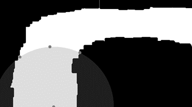
The computer science sub-team created the algorithms and interfaces for the autonomous vehicle. This included working on state estimation, computer vision, path planning, embedded programming, and actuator control. For state estimation, computer vision, and path planning, we utilized a variety of sensors to try to estimate our position and determine what our path should be. Specifically, we were using a GPS unit, IMU, motor encoders, LIDAR, and a depth camera. To determine the state of our robot, an Extended Kalman Filter would fuse the data collected from the GPS unit, IMU, and encoders. To determine what path the robot should take, the robot would detect obstacles using the LIDAR unit and the depth camera. With the camera, image thresholding was used to determine where the lines were and then noise reduction algorithms were used to give a better representation of the lines. Once the lines were converted into obstacles and the obstacles from the LIDAR coalesce, an obstacle map could be created. From this, we could utilize the A-Star algorithm to plan our path forward. We were also learning more about embedded programming and actuator control. Some of this past semester’s tasks included configuring an E-stop transmitter using MicroPython and reducing our error in the rotation of our separate steering motors. Both of these projects were the backbone, so to speak, of our robot to make sure that it was safe and that it was easily controllable. Overall, it was a very fun project!
 Sample Map for A-Star Navigation
Competition Results IGVC was split into two parts, a design competition, and a robot performance competition. For the design competition, the team had to present different components of the robot design and the innovations involved, and the judges inspected the robot. The team made it through the first round of presentations to become one of six finalists, and won 4th place! We were very happy with this result as this is the first time the team has attended IGVC. For the robot performance side, several unexpected failures occurred during the competition. During some testing with manual drive, parts of the wheel mounts had several malfunctions, including the casing of a gearbox splitting in half. There were also several issues with the integration of computer vision and path-planning algorithms. Despite this, with continued effort from team members, and lots of help, the robot was able to partly qualify and complete a small amount of the final course. In addition to the design and performance awards, we were awarded the Rookie of the Year award. This award is given to the best performing team out of those who are new to this competition. It is scored off of both the design and performance parts of IGVC. So, in addition to earning a design award, the team also took home Rookie of the Year! While the competition this year did not go as expected, we learned many things that we can put to use in both this year's robot and future ones. If the team decides to return to IGVC next year, we will continue to make improvements to the robot, and come back better!